
The Concrete Design add-on provides you with the option to perform the simplified fire resistance design according to EN 1992‑1‑2 for columns (Section 5.3.2) and beams (Section 5.6).
The following design checks are available for the simplified fire resistance design:
- Columns: Minimum cross-sectional dimensions for rectangular and circular sections according to Table 5.2a as well as Equation 5.7 for calculating time of fire exposure
- Beams: Minimum dimensions and center distances according to Table 5.5 and Table 5.6
You can determine the internal forces for the fire resistance design according to two methods.
- 1 Here, the internal forces of the accidental design situation are included directly into the design.
- 2 The internal forces of the design at normal temperature are reduced by the factor Eta,fi (ηfi), then used in the fire resistance design.
Furthermore, it is possible to modify the axis distance according to Eq. 5.5.

- Calculation of deflections and comparison with the normative or manually adjusted limit values
- Consideration of a precamber for the deflection analysis
- Different limit values are possible, depending on the design situation type
- Manual Adjustment of Reference Lengths and Segmentation by Direction
- Calculation of deflections related to the initial structure or to the deformed structure
- Further detailed design checks depending on the selected design standard (for example, vibration design according to EN 1999‑1‑1, 7.2.3)
- Graphical result display integrated in RFEM/RSTAB; for example, the design ratio of a limit value, or the deformation or the sag
- Complete integration of the results into the RFEM/RSTAB printout report

For the design according to Eurocode 9, you find the parameters of the National Annexes (NA) integrated for the following countries:
-
 DIN EN 1999-1-1/NA:2021-03 (Germany)
 -
 ÖNORM EN 1999-1-1/NA:2017-11 (Austria)
 -
 SN EN 1999-1-1/NA:2015-01 (Switzerland)
 -
 BDS EN 1999-1-1/NA:2014-05 (Bulgaria)
 -
 BS EN 1999-1-1/NA:2014-03 (United Kingdom)
 -
 CEN 1999-1-1/2013-12 (European Union)
 -
 CYS EN 1999-1-1/NA:2019-08 (Cyprus)
 -
 CZE EN 1999-1-1/NA:2015-09 (Czech Republic)
 -
 DS EN 1999-1-1/NA:2019-09 (Denmark)
 -
 ELOT EN 1999-1-1/NA:2013-12 (Greece)
 -
 EVS EN 1999-1-1/NA:2014-01 (Estonia)
 -
 HRN EN 1999-1-1/NA:2015-02 (Croatia)
 -
 I S. EN 1999-1-1/NA:2015-01 (Ireland)
 -
 ILNAS EN 1999-1-1/NA:2013-12 (Luxembourg)
 -
 IST EN 1999-1-1/NA:2014-03 (Iceland)
 -
 LST EN 1999-1-1/NA:2014-03 (Lithuania)
 -
 LVS EN 1999-1-1/NA:2015-01 (Latvia)
 -
 MSZ EN 1999-1-1/NA:2014-04 (Hungary)
 -
 NBN EN 1999-1-1/NA:2014-01 (Belgium)
 -
 NEN EN 1999-1-1/NA:2014-01 (Netherlands)
 -
 NF EN 1999-1-1/NA:2016-07 (France)
 -
 NP EN 1999-1-1/NA:2014-11 (Portugal)
 -
 NS EN 1999-1-1/NA:2014-04 (Norway)
 -
 PN EN 1999-1-1/NA:2014-05 (Poland)
 -
 SFS EN 1999-1-1/NA:2018-01 (Finland)
 -
 SIST EN 1999-1-1/NA:2014-05 (Slovenia)
 -
 SR EN 1999-1-1/NA:2015-01 (Romania)
 -
 SS EN 1999-1-1/NA:2013-12 (Sweden)
 -
 STN EN 1999-1-1/NA:2014-05 (Slovakia)
 -
 TKP EN 1999-1-1/NA:2010-01 (Belarus)
 -
 UNE EN 1999-1-1/NA:2014-01 (Spain)
 -
 UNI EN 1999-1-1/NA:2014-02 (Italy)

RFEM 6 and RSTAB 9 support the ergonomically optimized utilization of a mobile 3D mouse by 3Dconnexion.
With a 3D mouse, you can simultaneously move, zoom, and flip a 3D model on the screen beyond the use of a regular mouse. The 3D mouse complements the conventional computer mouse and is operated with your free hand. Therefore, you can streamline the workflow if you operate a 3D mouse with your non-dominant hand, in addition to the normal mouse.
.png?mw=640&hash=25998fe3470f8e1c154828f202ad6a728b30f00a)
Did you know that To calculate masonry structures, a nonlinear material model has been implemented in RFEM. It is based on the approach of Lourenco, a composite yield surface according to Rankine and Hill. This model allows you to describe and model the structural behavior of masonry and the different failure mechanisms.
The limit parameters were selected in such a way that the design curves used correspond to a normative design curve.

For the design according to Eurocode 5, the parameters of the National Annexes (NA) are integrated for the following countries:
-
DIN EN 1995-1-1/NA:2014-07 (Germany)
-
ÖNORM EN 1995-1-1/NA:2019-06 (Austria)
-
SN EN 1995-1-1/NA:2015-03 (Switzerland)
-
BDS EN 1995-1-1/NA:20157-06 (Bulgaria)
-
BS EN 1995-1-1/NA:2019-09 (United Kingdom)
-
CEN EN 1995-1-1/2014-05 (European Union)
-
CYS EN 1995-1-1/NA:2019-06 (Cyprus)
-
CZE EN 1995-1-1/NA:2015-05 (Czech Republic)
-
DS EN 1995-1-1/NA:2019-09 (Denmark)
-
ELOT EN 1995-1-1/NA:2010-01 (Greece)
-
EVS EN 1995-1-1/NA:2015-11 (Estonia)
-
HRN EN 1995-1-1/NA:2015-03 (Croatia)
-
I S. EN 1995-1-1/NA:2014-05 (Ireland)
-
ILNAS EN 1995-1-1/NA:2020-3 (Luxembourg)
-
IST EN 1995-1-1/NA:2014-09 (Iceland)
-
LST EN 1995-1-1/NA:2014-06 (Lithuania)
-
LVS EN 1995-1-1/NA:2014-12 (Latvia)
-
MSZ EN 1995-1-1/NA:2015-06 (Hungary)
-
NBN EN 1995-1-1/NA:2014-06 (Belgium)
-
NEN EN 1995-1-1/NA:2014-06 (Netherlands)
-
NF EN 1995-1-1/NA:2020-04 (France)
-
NP EN 1995-1-1/NA:2014-09 (Portugal)
-
NS EN 1995-1-1/NA:2014-08 (Norway)
-
PN EN 1995-1-1/NA:2014-07 (Poland)
-
SFS EN 1995-1-1/NA:2016-12 (Finland)
-
SIST EN 1995-1-1/NA:2018-01 (Slovenia)
-
SR EN 1995-1-1/NA:2014-12 (Romania)
-
 SS EN 1995-1-1/NA:2018-02 (Singapore)
 -
SS EN 1995-1-1/NA:2014-05 (Sweden)
-
STN EN 1995-1-1/NA:2019-12 (Slovakia)
-
TKP EN 1995-1-1/NA:2019-09 (Belarus)
-
UNE EN 1995-1-1/NA:2016-04 (Spain)
-
UNI EN 1995-1-1/NA:2016-11 (Italy)

- Calculation of deflections and comparison with the normative or manually adjusted limit values
- Consideration of a precamber for the deflection analysis
- Different limit values are possible, depending on the design situation type
- Manual adjustment of reference lengths and segmentation by direction
- Calculation of deflections related to the initial structure or to the deformed structure
- Automatic consideration of time-dependent deformations by increasing the load with the creep factor (can also be user-defined on the stiffness side)
- Simplified vibration design
- Graphical result display integrated in RFEM/RSTAB; for example, the design ratio of a limit value, the deformation, or the sag
- Complete integration of the results into the RFEM/RSTAB printout report

- Calculation of deflections and comparison with the normative or manually adjusted limit values
- Consideration of a precamber for the deflection analysis
- Different limit values are possible, depending on the design situation type
- Manual adjustment of reference lengths and segmentation by direction
- Calculation of deflections related to the initial structure or to the deformed structure
- Further detailed design checks depending on the selected design standard (for example, limitation of web breathing according to EN 1993‑2)
- Graphical result display integrated in RFEM/RSTAB; for example, the design ratio of a limit value, the deformation, or the sag
- Complete integration of the results into the RFEM/RSTAB printout report
For the design according to Eurocode 3, the parameters of the National Annexes (NA) are integrated for the following countries:
-
DIN EN 1993-1-1/NA:2020-11 (Germany)
-
ÖNORM EN 1993-1-1/NA:2015-12 (Austria)
-
SN EN 1993-1-1/NA:2016-07 (Switzerland)
-
BDS EN 1993-1-1/NA:2015-10 (Bulgaria)
-
BS EN 1993-1-1/NA:2016-07 (United Kingdom)
-
CEN EN 1993-1-1/2015-06 (European Union)
-
CYS EN 1993-1-1/NA:2015-07 (Cyprus)
-
CZE EN 1993-1-1/NA:2016-06 (Czech Republic)
-
DS EN 1993-1-1/NA:2015-07 (Denmark)
-
ELOT EN 1993-1-1/NA:2017-01 (Greece)
-
EVS EN 1993-1-1/NA:2015-08 (Estonia)
-
HRN EN 1993-1-1/NA:2016-03 (Croatia)
-
I S. EN 1993-1-1/NA:2016-03 (Ireland)
-
ILNAS EN 1993-1-1/NA:2015-06 (Luxembourg)
-
IST EN 1993-1-1/NA:2015-11 (Iceland)
-
LST EN 1993-1-1/NA:2017-01 (Lithuania)
-
LVS EN 1993-1-1/NA:2015-10 (Latvia)
-
 MS EN 1993-1-1/NA:2010-01 (Malaysia)
 -
MSZ EN 1993-1-1/NA:2015-11 (Hungary)
-
NBN EN 1993-1-1/NA:2015-07 (Belgium)
-
NEN EN 1993-1-1/NA:2016-12 (Netherlands)
-
NF EN 1993-1-1/NA:2016-02 (France)
-
NP EN 1993-1-1/NA:2009-03 (Portugal)
-
NS EN 1993-1-1/NA:2015-09 (Norway)
-
PN EN 1993-1-1/NA:2015-08 (Poland)
-
SFS EN 1993-1-1/NA:2015-08 (Finland)
-
SIST EN 1993-1-1/NA:2016-09 (Slovenia)
-
SR EN 1993-1-1/NA:2016-04 (Romania)
-
SS EN 1993-1-1/NA:2019-05 (Singapore)
-
SS EN 1993-1-1/NA:2015-06 (Sweden)
-
STN EN 1993-1-1/NA:2015-10 (Slovakia)
-
TKP EN 1993-1-1/NA:2015-04 (Belarus)
-
UNE EN 1993-1-1/NA:2016-02 (Spain)
-
UNI EN 1993-1-1/NA:2015-08 (Italy)

Compared to the RF‑/TIMBER Pro add-on module (RFEM 5 / RSTAB 8), the following new features have been added to the Timber Design add-on for RFEM 6 / RSTAB 9:
- In addition to Eurocode 5, other international standards are integrated (SIA 265, ANSI/AWC NDS, CSA O86, GB 50005)
- Design of compression perpendicular to grain (support pressure)
- Implementation of eigenvalue solver for determining the critical moment for lateral-torsional buckling (EC 5 only)
- Definition of different effective lengths for design at normal temperature and fire resistance design
- Evaluation of stresses via unit stresses (FEA)
- Optimized stability analyses for tapered members
- Unification of the materials for all national annexes (only one "EN" standard is now available in the material library for a better overview)
- Display of cross-section weakenings directly in the rendering
- Output of the used design check formulas (including a reference to the used equation from the standard)

Compared to the RF‑/STABILITY (RFEM 5) and RSBUCK (RSTAB 8) add-on modules, the following new features have been added to the Structure Stability add-on for RFEM 6 / RSTAB 9:
- Activation as a property of a load case or a load combination
- Automated activation of the stability calculation via combination wizards for several load situations in one step
- Incremental load increase with user-defined termination criteria
- Modification of the mode shape normalization without recalculation
- Result tables with filter option

- For the design according to Eurocode 3, the parameters of the National Annexes (NA) are integrated for the following countries:
-
DIN EN 1993-1-1/NA:2016-04 (Germany)
-
ÖNORM EN 1993-1-1/NA:2015-12 (Austria)
-
SN EN 1993-1-1/NA:2016-07 (Switzerland)
-
BDS EN 1993-1-1/NA:2015-10 (Bulgaria)
-
BS EN 1993-1-1/NA:2016-07 (United Kingdom)
-
CEN EN 1993-1-1/2015-06 (European Union)
-
CYS EN 1993-1-1/NA:2015-07 (Cyprus)
-
CZE EN 1993-1-1/NA:2016-06 (Czech Republic)
-
DS EN 1993-1-1/NA:2015-07 (Denmark)
-
ELOT EN 1993-1-1/NA:2017-01 (Greece)
-
EVS EN 1993-1-1/NA:2015-08 (Estonia)
-
HRN EN 1993-1-1/NA:2016-03 (Croatia)
-
I S. EN 1993-1-1/NA:2016-03 (Ireland)
-
ILNAS EN 1993-1-1/NA:2015-06 (Luxembourg)
-
IST EN 1993-1-1/NA:2015-11 (Iceland)
-
LST EN 1993-1-1/NA:2017-01 (Lithuania)
-
LVS EN 1993-1-1/NA:2015-10 (Latvia)
-
MS EN 1993-1-1/NA:2010-01 (Malaysia)
-
MSZ EN 1993-1-1/NA:2015-11 (Hungary)
-
NBN EN 1993-1-1/NA:2015-07 (Belgium)
-
NEN EN 1993-1-1/NA:2016-12 (Netherlands)
-
NF EN 1993-1-1/NA:2016-02 (France)
-
NP EN 1993-1-1/NA:2009-03 (Portugal)
-
NS EN 1993-1-1/NA:2015-09 (Norway)
-
PN EN 1993-1-1/NA:2015-08 (Poland)
-
SFS EN 1993-1-1/NA:2015-08 (Finland)
-
SIST EN 1993-1-1/NA:2016-09 (Slovenia)
-
SR EN 1993-1-1/NA:2016-04 (Romania)
-
SS EN 1993-1-1/NA:2019-05 (Singapore)
-
SS EN 1993-1-1/NA:2015-06 (Sweden)
-
STN EN 1993-1-1/NA:2015-10 (Slovakia)
-
TKP EN 1993-1-1/NA:2015-04 (Belarus)
-
UNE EN 1993-1-1/NA:2016-02 (Spain)
-
UNI EN 1993-1-1/NA:2015-08 (Italy)
-
- The design according to US standard AISC 360 includes analysis methods according to:
-
 Load and Resistance Factor Design (LRFD)
 -
Allowable Stress Design (ASD)
-

The parameters of the National Annexes (NA) to Eurocode 3 of the following countries are integrated:
-
DIN EN 1993-1-1/NA:2016-04 (Germany)
-
ÖNORM EN 1993-1-1/NA:2015-12 (Austria)
-
SN EN 1993-1-1/NA:2016-07 (Switzerland)
-
BDS EN 1993-1-1/NA:2015-10 (Bulgaria)
-
BS EN 1993-1-1/NA:2016-07 (United Kingdom)
-
CEN EN 1993-1-1/2015-06 (European Union)
-
CYS EN 1993-1-1/NA:2015-07 (Cyprus)
-
CSN EN 1993-1-1/NA:2016-06 (Czech Republic)
-
DS EN 1993-1-1/NA:2015-07 (Denmark)
-
ELOT EN 1993-1-1/NA:2017-01 (Greece)
-
EVS EN 1993-1-1/NA:2015-08 (Estonia)
-
HRN EN 1993-1-1/NA:2016-03 (Croatia)
-
I S. EN 1993-1-1/NA:2016-03 (Ireland)
-
ILNAS EN 1993-1-1/NA:2015-06 (Luxembourg)
-
IST EN 1993-1-1/NA:2015-11 (Iceland)
-
LST EN 1993-1-1/NA:2017-01 (Lithuania)
-
LVS EN 1993-1-1/NA:2015-10 (Latvia)
-
MS EN 1993-1-1/NA:2010-01 (Malaysia)
-
MSZ EN 1993-1-1/NA:2015-11 (Hungary)
-
NBN EN 1993-1-1/NA:2015-07 (Belgium)
-
NEN EN 1993-1-1/NA:2016-12 (Netherlands)
-
NF EN 1993-1-1/NA:2016-02 (France)
-
NP EN 1993-1-1/NA:2009-03 (Portugal)
-
NS EN 1993-1-1/NA:2015-09 (Norway)
-
PN EN 1993-1-1/NA:2015-08 (Poland)
-
SFS EN 1993-1-1/NA:2015-08 (Finland)
-
SIST EN 1993-1-1/NA:2016-09 (Slovenia)
-
SR EN 1993-1-1/NA:2016-04 (Romania)
-
SS EN 1993-1-1/NA:2019-05 (Singapore)
-
SS EN 1993-1-1/NA:2015-06 (Sweden)
-
STN EN 1993-1-1/NA:2015-10 (Slovakia)
-
TKP EN 1993-1-1/NA:2015-04 (Belarus)
-
UNE EN 1993-1-1/NA:2016-02 (Spain)
-
UNI EN 1993-1-1/NA:2015-08 (Italy)

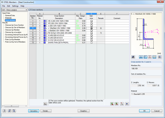
- Cross-section optimization
- Transfer of optimized sections to RFEM/RSTAB
- Design of any thin-walled section from RSECTION
- Representation of a stress diagram on a section
- Determination of normal, shear, and equivalent stresses
- Output of stress components for the individual member internal force types
- Detailed representation of stresses in all stress points
- Determination of the largest Δσ for each stress point (for example, for fatigue design)
- Colored display of stresses and design ratios for a quick overview of the critical or oversized zones
- Output of parts lists

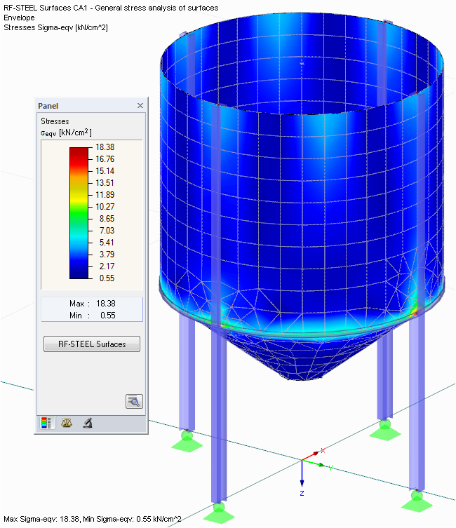
- Determination of principal and basic stresses, membrane and shear stresses, as well as equivalent stresses and equivalent membrane stresses
- Stress analysis for structural surfaces including simple or complex shapes
- Equivalent stresses calculated according to different approaches:
- Shape modification hypothesis (von Mises)
- Shear stress hypothesis (Tresca)
- Normal stress hypothesis (Rankine)
- Principal strain hypothesis (Bach)
- Optional optimization of surface thicknesses and data transfer to RFEM
- Output of strains
- Detailed results of individual stress components and ratios in tables and graphics
- Filter function for solids, surfaces, lines, and nodes in tables
- Transversal shear stresses according to Mindlin, Kirchhoff, or user-defined specifications
- Stress evaluation for welds at connection lines between surfaces (see the Product Feature)
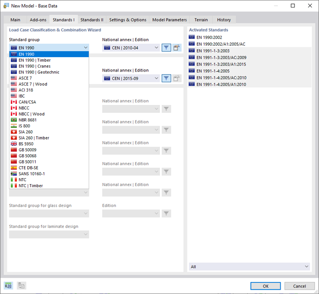
With Dlubal, you can safely and easily design structures all over the world. Select from a large number of standards in the Base Data. You can also decide whether to create the combinations automatically.
The following standards are available:
-
EN 1990
-
EN 1990 | Timber
-
EN 1990 | Road Bridges
-
EN 1990 | Cranes
-
EN 1990 | Geotechnical Engineering
-
EN 1990 | Base + Timber
-
EN 15512
-
ASCE 7
-
ASCE 7 | Timber
-
ACI 318
-
IBC
-
 CAN/CSA
 -
NBC
-
NBC | Timber
-
 NBR 8681
 -
 IS 800
 -
SIA 260
-
SIA 260 | Timber
-
BS 5950
-
 GB 50009
 -
GB 50068
-
GB 50011
-
CTE DB-SE
-
 SANS 10160-1
 -
 NTC
NTC -
NTC | Timber
-
 AS/NZS 1170.0
 -
 SP 20.13330:2016
 -
 TSC | Steel
For the European standards (EC), the following National Annexes are available:
-
DIN | 2012-08 (Germany)
-
CEN | 2010-04 (European Union)
-
BDS | 2013-03 (Bulgaria)
-
BS | 2009-06 (United Kingdom)
-
CSN | 2015-05 (Czech Republic)
-
CYS | 2010-06 (Cyprus)
-
DK | 2013-09 (Denmark)
-
ELOT | 2009-01 (Greece)
-
EVS-EN 1990:2002+NA:2002 (Estonia)
-
IS | 2010-04 (Ireland)
-
LST | 2012-01 (Lithuania)
-
LU | 2020-03 (Luxembourg)
-
LVS | 2015-01 (Latvia)
-
MS | 2010-02 (Malaysia)
-
NBN | 2015-05 (Belgium)
-
NEN | 2011-12 (Netherlands)
-
NF | 2011-12 (France)
-
NP | 2009-12 (Portugal)
-
NS | 2016-05 (Norway)
-
ÖNORM | 2013-03 (Austria)
-
PN | 2010-09 (Poland)
-
SFS | 2010-09 (Finland)
-
SIST | 2010-08 (Slovenia)
-
SR | 2006-10 (Romania)
-
SS | 2008-06 (Singapore)
-
SS | 2019-01 (Sweden)
-
STN | 2010-01 (Slovakia)
-
TKP | 2011-11 (Belarus)
-
UNE | 2010-07 (Spain)
-
UNI | 2010-10 (Italy)
Plan your buildings safely and according to the European standards. In both main programs RFEM 6 and RSTAB 9, you can easily and efficiently generate load and result combinations according to Eurocode 0 (EN 1990). Furthermore, it is also possible to determine imperfections according to Eurocode in both programs. The actions are assigned to the action types of the standard. RFEM and RSTAB then combine the load cases according to the selected design situations.
Automatic Generation of Load CombinationsThe following National Annexes are available:
-
DIN | 2012-08 (Germany)
-
CEN | 2010-04 (European Union)
-
BDS | 2013-03 (Bulgaria)
-
BS | 2009-06 (United Kingdom)
-
CSN | 2015-05 (Czech Republic)
-
CYS | 2010-06 (Cyprus)
-
DK | 2013-09 (Denmark)
-
ELOT | 2009-01 (Greece)
-
EVS-EN 1990:2002+NA:2002 (Estonia)
-
IS | 2010-04 (Ireland)
-
LST | 2012-01 (Lithuania)
-
LU | 2020-03 (Luxembourg)
-
LVS | 2015-01 (Latvia)
-
MS | 2010-02 (Malaysia)
-
NBN | 2015-05 (Belgium)
-
NEN | 2011-12 (Netherlands)
-
NF | 2011-12 (France)
-
NP | 2009-12 (Portugal)
-
NS | 2016-05 (Norway)
-
ÖNORM | 2013-03 (Austria)
-
PN | 2010-09 (Poland)
-
SFS | 2010-09 (Finland)
-
SIST | 2010-08 (Slovenia)
-
SR | 2006-10 (Romania)
-
SS | 2008-06 (Singapore)
-
SS | 2019-01 (Sweden)
-
STN | 2010-01 (Slovakia)
-
TKP | 2011-11 (Belarus)
-
UNE | 2010-07 (Spain)
-
UNI | 2010-10 (Italy)
_(2).png?mw=640&hash=0414bfe44045fc798e3774a0173332ca37424418)
General
- Beam to Column joint category: connection possible as joint of the beam to the column flange as well as joint of the column to the girder flange
- Beam to Beam joint category: design of beam joints as both moment-resisting end plate connections and rigid splice connections possible
- Automatic export of model and load data possible from RFEM or RSTAB
- Bolt sizes from M12 to M36 with strength grades 4.6, 4.8, 5.6, 5.8, 6.8, 8.8, and 10.9 as long as the strength grades are available in the selected National Annex
- Almost any bolt spacing and edge distances (a check of the allowable distances is performed)
- Beam strengthening with tapers or stiffeners on the top and bottom surfaces
- End plate connection with and without overlap
- Connection with pure bending stress, pure normal force load (tension joint), or combination of normal force and bending possible
- Calculation of connection stiffnesses and check if a hinged, semi-rigid, or rigid connection exists
End plate connection in a beam-column setup
- Joint beams or columns can be stiffened with tapers on one side or with stiffeners to one or both sides
- Wide range of possible stiffeners of the connection (for example, complete or incomplete web stiffeners)
- Up to ten horizontal and four vertical bolts possible
- Connected object possible as constant or tapered I-section
- Designs:
- Ultimate limit state of the connected beam (such as shear or tension resistance of the web plate)
- Ultimate limit state of the end plate at the beam (for example, T-stub under tensile stress)
- Ultimate limit state of the welds at the end plate
- Ultimate limit state of the column in the area of the connection (for example, column flange under bending – T-stub)
- All designs are performed according to EN 1993-1-8 and EN 1993-1-1
Moment-resisting end plate joint
- Two or four vertical and up to 10 horizontal bolt rows
- Joint beams can be stiffened with tapers on one side or with stiffeners to one or both sides
- Connected objects are possible as constant or tapered I-sections
- Designs:
- Ultimate limit state of the connected beams (such as shear or tension resistance of the web plates)
- Ultimate limit state of the end plates at the beam (for example, T-stub under tensile stress)
- Ultimate limit state of the welds at the end plates
- Ultimate limit state of the bolts in the end plate (combination of tension and shear)
Rigid splice plate connection
- For the flange plate connection, up to ten bolt rows one behind the other possible
- For the web plate connection, up to ten bolt rows possible each in vertical and horizontal directions
- Material of the cleat can be different from the one of the beams
- Designs:
- Ultimate limit state of the joint beams (for example, net cross-section in the tension area)
- Ultimate limit state of the cleat plates (for example, net cross-section under tensile stress)
- Ultimate limit state of the single bolts and the bolt groups (for example, shear resistance design of the single bolt)
- Cross-section optimization
- Transfer of optimized sections to RFEM/RSTAB
- Design of any thin-walled cross-section from SHAPE-THIN
- Representation of a stress diagram on a section
- Determination of normal, shear, and equivalent stresses
- Stress results of individual internal forces types
- Detailed representation of stresses in all stress points
- Determination of the largest Δσ for each stress point (for example, for fatigue design)
- Colored display of stresses and design ratios for a quick overview of the critical or oversized zones
- Parts lists and quantity surveying
- Determination of principal and basic stresses, membrane and shear stresses, as well as equivalent stresses and equivalent membrane stresses
- Stress analysis for structural surfaces including simple or complex shapes
- Equivalent stresses calculated according to different approaches:
- Shape modification hypothesis (von Mises)
- Shear stress hypothesis (Tresca)
- Normal stress hypothesis (Rankine)
- Principal strain hypothesis (Bach)
- Optional optimization of surface thicknesses and data transfer to RFEM
- Serviceability limit state design by checking surface displacements
- Detailed results of individual stress components and ratios in tables and graphics
- Filter function for surfaces, lines, and nodes in tables
- Transversal shear stresses according to Mindlin, Kirchhoff, or user-defined specifications
- Parts list of designed surfaces
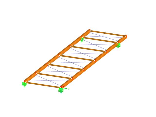
- Design of the following roof types:
- Monopitch roof
- Duopitch Roof
- Curved roof
- All roof shapes allow for a free selection of stiffening diagonals. The following types are available:
- Falling diagonals
- Rising diagonals
- Crossing diagonals with verticals
- Crossing diagonals without verticals
- Crossing diagonals with steel strips (ties)
- Consideration of window rows in the ridge by selecting an inner intermediate part.
- For design according to EC 5 (EN 1995), the following National Annexes are available:
-
DIN EN 1995-1-1/NA:2013-08 (Germany)
-
NBN EN 1995-1-1/ANB:2012-07 (Belgium)
-
DK EN 1995-1-1/NA:2011-12 (Denmark)
-
SFS EN 1995-1-1/NA:2007-11 (Finland)
-
NF EN 1995-1-1/NA:2010-05 (France)
-
UNI EN 1995-1-1/NA:2010-09 (Italy)
-
NEN EN 1995-1-1/NB:2007-11 (Netherlands)
-
ÖNORM B 1995-1-1:2015-06 (Austria)
-
PN EN 1995-1-1/NA:2010-09 (Poland)
-
SS EN 1995-1-1 (Sweden)
-
STN EN 1995-1-1/NA:2008-12 (Slovakia)
-
SIST EN 1995-1-1/A101:2006-03 (Slovenia)
-
CSN EN 1995-1-1:2007-09 (Czech Republic)
-
BS EN 1995-1-1/NA:2009-10 (the United Kingdom)
-
- Simple geometry input with illustrative graphics
- Automatic generation of wind loads
- Automatic creation of required combinations for the ultimate and serviceability limit states, as well as fire resistance design
- Free definition of the load cases to be used
- Extensive material library
- Optional extension of material library by further materials
- Extensive library of permanent loads
- Allocation of framework to service classes and specification of service class categories
- Determination of design ratios, support forces, and deformations
- Info icon indicating successful or failed design
- Color reference scales in result tables
- Direct data export to MS Excel
- DXF interface for preparation production documents in CAD
- Program languages: English, German, Czech, Italian, Spanish, French, Portuguese, Polish, Chinese, Dutch, and Russian
- Verifiable printout report, including all required designs. Printout report available in many output languages; for example, English, German, French, Italian, Spanish, Russian, Czech, Polish, Portuguese, Chinese, and Dutch.
- In the ultimate limit state design, the stiffness of the hinge is divided by the partial safety factor and in the serviceability limit state design calculated using the mean stiffnesses. The limit values for the ultimate and the serviceability limit states can be defined separately.
- Design of the following geometrical types:
- Single-span beams with and without cantilevers
- Continuous beams with and without cantilevers
- Hinged girder system (Gerber beams) with and without cantilevers
- Automatic generation of wind and snow loads
- Automatic creation of required combinations for the ultimate and serviceability limit states, as well as fire resistance design
- For design according to EC 5 (EN 1995), the following National Annexes are available:
-
DIN EN 1995-1-1/NA:2013-08 (Germany)
-
NBN EN 1995-1-1/ANB:2012-07 (Belgium)
-
DK EN 1995-1-1/NA:2011-12 (Denmark)
-
SFS EN 1995-1-1/NA:2007-11 (Finland)
-
NF EN 1995-1-1/NA:2010-05 (France)
-
UNI EN 1995-1-1/NA:2010-09 (Italy)
-
NEN EN 1995-1-1/NB:2007-11 (Netherlands)
-
ÖNORM B 1995-1-1:2015-06 (Austria)
-
PN EN 1995-1-1/NA:2010-09 (Poland)
-
SS EN 1995-1-1 (Sweden)
-
STN EN 1995-1-1/NA:2008-12 (Slovakia)
-
SIST EN 1995-1-1/A101:2006-03 (Slovenia)
-
CSN EN 1995-1-1:2007-09 (Czech Republic)
-
BS EN 1995-1-1/NA:2009-10 (the United Kingdom)
-
- Consideration of optimization options by user specifications according to the respective standard:
- Shear force reduction of single loads near support
- Shear force reduction of load introduction at the cross-section top point
- Moment redistribution in support zone
- Reduction of torsional stress by means of user-defined entry of moment
- Increase of bending stiffnesses for flat-ended or edgewise bending strains
- Simple geometry input with illustrative graphics
- Extensive material library for both standards
- Optional extension of material library by further materials
- Extensive library of permanent loads
- Allocation of framework to service classes and specification of service class categories
- Determination of design ratios, support forces, and deformations
- Info icon indicating successful or failed design
- Color reference scales in result tables
- Direct data export to MS Excel
- Program languages: English, German, Czech, Italian, Spanish, French, Portuguese, Polish, Chinese, Dutch, and Russian
- Verifiable printout report, including all required designs. Printout report available in many output languages; for example, English, German, French, Italian, Spanish, Russian, Czech, Polish, Portuguese, Chinese, and Dutch.
- Direct import of stp files from various CAD programs
- Design of the following column types:
- Hinged column, optionally with elastic restraint of head or footing
- Bracket, optionally with elastic restraint of footing
- Simple geometry input with illustrative graphics
- Extensive material library
- Allocation of framework to service classes and specification of service class categories
- Detailed settings of the fire resistance design
- Specification of limit deformation for the serviceability limit state design
- Determination of design ratios, support forces, and deformations
- For design according to EC 5 (EN 1995), the following National Annexes are available:
-
DIN EN 1995-1-1/NA:2013-08 (Germany)
-
NBN EN 1995-1-1/ANB:2012-07 (Belgium)
-
DK EN 1995-1-1/NA:2011-12 (Denmark)
-
SFS EN 1995-1-1/NA:2007-11 (Finland)
-
NF EN 1995-1-1/NA:2010-05 (France)
-
UNI EN 1995-1-1/NA:2010-09 (Italy)
-
NEN EN 1995-1-1/NB:2007-11 (Netherlands)
-
ÖNORM B 1995-1-1:2015-06 (Austria)
-
PN EN 1995-1-1/NA:2010-09 (Poland)
-
SS EN 1995-1-1 (Sweden)
-
STN EN 1995-1-1/NA:2008-12 (Slovakia)
-
SIST EN 1995-1-1/A101:2006-03 (Slovenia)
-
CSN EN 1995-1-1:2007-09 (Czech Republic)
-
BS EN 1995-1-1/NA:2009-10 (the United Kingdom)
- Automatic generation of wind and snow loads
- Multiple optional reductions according to the selected standard
- Direct data export to MS Excel
- Program languages: English, German, Czech, Italian, Spanish, French, Portuguese, Polish, Chinese, Dutch, and Russian
- Verifiable printout report, including all required designs. Printout report available in many output languages; for example, English, German, French, Italian, Spanish, Russian, Czech, Polish, Portuguese, Chinese, and Dutch.
- Direct import of stp files from various CAD programs
- Design of the following geometrical types:
- Single-span beams with and without cantilevers
- Continuous beams with and without cantilevers
- Hinged girder system (Gerber beams) with and without cantilevers
- For design according to EC 5 (EN 1995), the following National Annexes are available:
-
DIN EN 1995-1-1/NA:2013-08 (Germany)
-
NBN EN 1995-1-1/ANB:2012-07 (Belgium)
-
DK EN 1995-1-1/NA:2011-12 (Denmark)
-
SFS EN 1995-1-1/NA:2007-11 (Finland)
-
NF EN 1995-1-1/NA:2010-05 (France)
-
UNI EN 1995-1-1/NA:2010-09 (Italy)
-
NEN EN 1995-1-1/NB:2007-11 (Netherlands)
-
ÖNORM B 1995-1-1:2015-06 (Austria)
-
PN EN 1995-1-1/NA:2010-09 (Poland)
-
SS EN 1995-1-1 (Sweden)
-
STN EN 1995-1-1/NA:2008-12 (Slovakia)
-
SIST EN 1995-1-1/A101:2006-03 (Slovenia)
-
CSN EN 1995-1-1:2007-09 (Czech Republic)
-
BS EN 1995-1-1/NA:2009-10 (the United Kingdom)
-
- Automatic generation of wind and snow loads
- Multiple optional reductions according to the selected standard
- Simple geometry input with illustrative graphics
- Free entry of tapered geometries. Free selection of the grain angle allows for user-defined design of the compressive and tensile areas for bending
- Comprehensive and extensible material library
- Determination of design ratios, support forces, and deformations
- Color reference scales in result tables
- Direct data export to MS Excel
- DXF interface for preparation production documents in CAD
- Program languages: English, German, Czech, Italian, Spanish, French, Portuguese, Polish, Chinese, Dutch, and Russian
- Verifiable printout report, including all required designs. Printout report available in many output languages; for example, English, German, French, Italian, Spanish, Russian, Czech, Polish, Portuguese, Chinese, and Dutch.
- Direct import of stp files from various CAD programs

- Import of materials, cross-sections, and internal forces from RFEM/RSTAB
- Steel design of thin‑walled cross‑sections according to EN 1993‑1‑1:2005 and EN 1993‑1‑5:2006
- Automatic classification of cross-sections according to EN 1993-1-1:2005 + AC:2009, Cl. 5.5.2, and EN 1993-1-5:2006, Cl. 4.4 (cross-section class 4), with optional determination of effective widths according to Annex E for stresses under fy
- Integration of parameters for the following National Annexes:
-
DIN EN 1993-1-1/NA:2015-08 (Germany)
-
ÖNORM B 1993-1-1:2007-02 (Austria)
-
NBN EN 1993-1-1/ANB:2010-12 (Belgium)
-
BDS EN 1993-1-1/NA:2008 (Bulgaria)
-
DS/EN 1993-1-1 DK NA:2015 (Denmark)
-
SFS EN 1993-1-1/NA:2005 (Finland)
-
NF EN 1993-1-1/NA:2007-05 (France)
-
ELOT EN 1993-1-1 (Greece)
-
UNI EN 1993-1-1/NA:2008 (Italy)
-
LST EN 1993-1-1/NA:2009-04 (Lithuania)
-
UNI EN 1993-1-1/NA:2011-02 (Italy)
-
MS EN 1993-1-1/NA:2010 (Malaysia)
-
NEN EN 1993-1-1/NA:2011-12 (Netherlands)
- NS EN 1993-1-1/NA:2008-02 (Norway)
-
PN EN 1993-1-1/NA:2006-06 (Poland)
-
NP EN 1993-1-1/NA:2010-03 (Portugal)
-
SR EN 1993-1-1/NB:2008-04 (Romania)
-
SS EN 1993-1-1/NA:2011-04 (Sweden)
-
SS EN 1993-1-1/NA:2010 (Singapore)
-
STN EN 1993-1-1/NA:2007-12 (Slovakia)
-
SIST EN 1993-1-1/A101:2006-03 (Slovenia)
-
UNE EN 1993-1-1/NA:2013-02 (Spain)
-
CSN EN 1993-1-1/NA:2007-05 (Czech Republic)
-
BS EN 1993-1-1/NA:2008-12 (the United Kingdom)
-
CYS EN 1993-1-1/NA:2009-03 (Cyprus)
- In addition to the National Annexes (NA) listed above, you can also define a specific NA, applying user‑defined limit values and parameters.
- Automatic calculation of all required factors for the design value of flexural buckling resistance Nb,Rd
- Automatic determination of the ideal elastic critical moment Mcr for each member or set of members on every x-location according to the Eigenvalue Method or by comparing moment diagrams. You only have to define the lateral intermediate supports.
- Design of tapered members, unsymmetric sections or sets of members according to the General Method as described in EN 1993-1-1, Cl. 6.3.4
- In the case of the General Method according to Cl. 6.3.4, optional application of "European lateral-torsional buckling curve" according to Naumes, Strohmann, Ungermann, Sedlacek (Stahlbau 77 [2008], pp. 748‑761)
- Rotational restraints can be taken into account (trapezoidal sheeting and purlins)
- Optional consideration of shear panels (for example, trapezoidal sheeting and bracing)
- RF-/STEEL Warping Torsion module extension (license required) for stability analysis according to the second-order analysis as stress analysis including consideration of the 7th degree of freedom (warping)
- Module extension RF-/STEEL Plasticity (license required) for plastic analysis of cross‑sections according to Partial Internal Forces Method (PIFM) and Simplex Method for general cross‑sections (in connection with the RF‑/STEEL Warping Torsion module extension, it is possible to perform the plastic design according to the second‑order analysis)
- Module extension RF-/STEEL Cold-Formed Sections (license required) for ultimate and serviceability limit state designs for cold-formed steel members according to the EN 1993-1-3 and EN 1993-1-5 standards
- ULS design: Selection of fundamental or accidental design situations for each load case, load combination, or result combination
- SLS design: Selection of characteristic, frequent, or quasi-permanent design situations for each load case, load combination, or result combination
- Tension analysis with definable net cross-section areas for member start and end
- Weld designs of welded cross-sections
- Optional calculation of warp spring for nodal support on sets of members
- Graphic of design ratios on cross-section and in RFEM/RSTAB model
- Determination of governing internal forces
- Filter options for graphical results in RFEM/RSTAB
- Representation of design ratios and cross‑section classes in the rendered view
- Color scales in result windows
- Automatic cross-section optimization
- Transfer of optimized cross-sections to RFEM/RSTAB
- Parts lists and quantity surveying
- Direct data export to MS Excel
- Verifiable printout report
- Possibility to include the temperature curve in the report
- Full integration in RFEM/RSTAB with import of geometry and load case data
- Automatic selection of members for design according to specified criteria (e.g. only vertical members)
- In connection with the extension EC2 for RFEM/RSTAB, you can perform the design of reinforced concrete compression elements according to the method based on nominal curvature in compliance with EN 1992 -1‑1:2004 (Eurocode 2) and the following National Annexes:
-
DIN EN 1992-1-1/NA/A1:2015-12 (Germany)
-
ÖNORM B 1992-1-1:2018-01 (Austria)
-
Belgium NBN EN 1992-1-1 ANB:2010 for design at normal temperature, and NBN EN 1992-1-2 ANB:2010 for fire resistance design (Belgium)
-
BDS EN 1992-1-1:2005/NA:2011 (Bulgaria)
-
EN 1992-1-1 DK NA:2013 (Denmark)
-
NF EN 1992-1-1/NA:2016-03 (France)
-
SFS EN 1992-1-1/NA:2007-10 (Finland)
-
UNI EN 1992-1-1/NA:2007-07 (Italy)
-
LVS EN 1992-1-1:2005/NA:2014 (Latvia)
-
LST EN 1992-1-1:2005/NA:2011 (Lithuania)
-
MS EN 1992-1-1:2010 (Malaysia)
-
NEN-EN 1992-1-1+C2:2011/NB:2016 (Netherlands)
-
NS EN 1992-1 -1:2004-NA:2008 (Norway)
-
PN EN 1992-1-1/NA:2010 (Poland)
-
NP EN 1992-1-1/NA:2010-02 (Portugal)
-
SR EN 1992-1-1:2004/NA:2008 (Romania)
-
SS EN 1992-1-1/NA:2008 (Sweden)
-
SS EN 1992-1-1/NA:2008-06 (Singapore)
-
STN EN 1992-1-1/NA:2008-06 (Slovakia)
-
SIST EN 1992-1-1:2005/A101:2006 (Slovenia)
-
UNE EN 1992-1-1/NA:2013 (Spain)
-
CSN EN 1992-1-1/NA:2016-05 (Czech Republic)
-
BS EN 1992-1-1:2004/NA:2005 (United Kingdom)
-
TKP EN 1992-1-1:2009 (Belarus)
-
CYS EN 1992-1-1:2004/NA:2009 (Cyprus)
-
- In addition to the National Annexes (NA) listed above, you can define a specific NA, applying user-defined limit values and parameters.
- Optional consideration of creep
- Diagram-based determination of buckling lengths and slenderness from the restraint ratios of columns
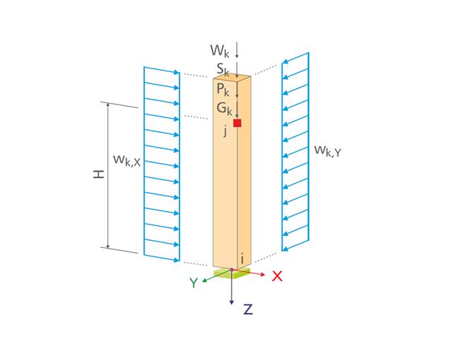
- Automatic determination of ordinary and unintentional eccentricity from additionally available eccentricity according to the second-order analysis
- Design of monolithic structures and precast elements
- Analysis with regard to the standard reinforced concrete design
- Determination of internal forces according to the linear static analysis and the second-order analysis
- Analysis of governing design locations along the column due to existing loading
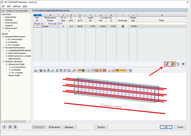
- Output of required longitudinal and stirrup reinforcement
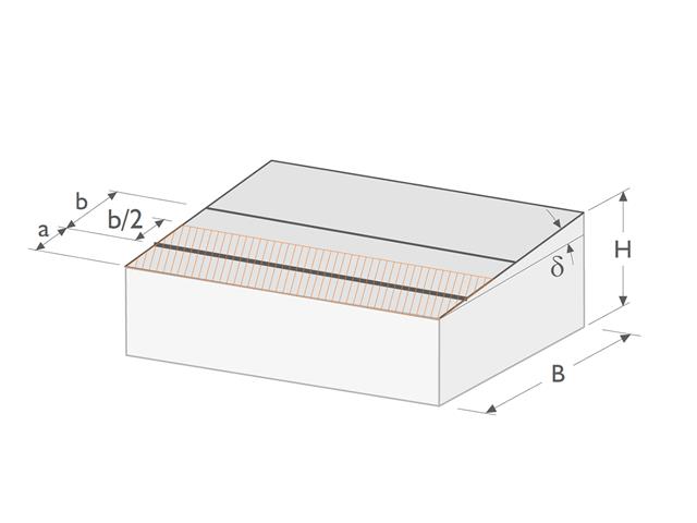
- Fire resistance design according to the simplified method (zone method) according to EN 1992-1-2 allowing the fire resistance design of brackets.
- Fire resistance design with optional longitudinal reinforcement design according to DIN 4102-22:2004 or DIN 4102-4:2004, Table 31
- Longitudinal and link reinforcement proposal with graphic display in 3D rendering
- Summary of design ratios, including all design details
- Graphical representation of relevant design details in RFEM/RSTAB work window
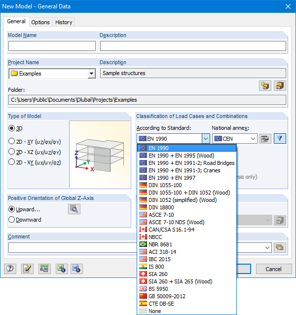
The Base Data dialog box includes a wide range of standards and the option to create combinations automatically. The following standards are available:
-
EN 1990:2002
-
EN 1990 + EN 1995:2004 (Timber)
-
EN 1990 + EN 1991-2; Road bridges
-
EN 1990 + EN 1991-3; Cranes
-
EN 1990 + EN 1997
-
to DIN 1055-100:2001-03
-
DIN 1055-100 + DIN 1052:2004-08 (timber)
-
DIN 1055-100 + DIN 18008 (Glass)
-
DIN 1052 (simplified) (timber)
-
DIN 18800:1990
-
ASCE 7‑10
-
ASCE 7-10 NDS (Wood)
-
ACI 318-14
-
IBC 2015
-
CAN/CSA S 16.1-94:1994
-
NBCC: 2005
-
NBR 8681
-
IS 800:2007
-
SIA 260:2003
-
SIA 260 + SIA 265:2003 (timber)
-
BS 5950-1:2000
-
GB 50009-2012
-
CTE DB-SE
For the European standards (EC), the following National Annexes are available:
-
DIN EN 1990/NA:2009-05 (Germany)
-
NBN EN 1990 - ANB: 2005 (Belgium)
-
BDS EN 1990:2003/NA:2008 (Bulgaria)
-
DK EN 1990/NA:2007-07 (Denmark)
-
SFS EN 1990/NA:2005 (Finland)
-
NF EN 1990/NA:2005/12 (France)
-
ELOT EN 1990:2009 (Greece)
-
UNI EN 1990/NA:2007-07 (Italy)
-
IS EN 1990:2002 + NA:2010 (Ireland)
-
LVS EN 1990:2003/NA:2010 (Latvia)
-
LST EN 1990/NA:2010-11 (Lithuania)
-
LU EN 1990/NA:2011-09 (Luxembourg)
-
MS EN 1990:2010 (Malaysia)
-
NEN EN 1990/NA:2006 (Netherlands)
- NS EN 1990/NA:2008 (Norway)
-
ÖNORM EN 1990:2007-02 (Austria)
-
NP EN 1990:2009 (Portugal)
-
PN EN 1990/NA:2004 (Poland)
-
SR EN 1990/NA:2006-10 (Romania)
-
SIST EN 1990: 2004/A1:2005 (Slovenia)
-
SS EN 1990:2008 (Singapore)
-
SS EN 1990/BFS 2010:28 (Sweden)
-
STN EN 1990/NA:2009-08 (Slovakia)
-
UNE EN 1990 2003 (Spain)
-
CSN EN 1990/NA:2004-03 (Czech Republic)
-
BS EN 1990/NA:2004-12 (the United Kingdom)
-
TKP EN 1990/NA:2011 (Belarus)
-
CYS EN 1990:2002 (Cyprus)
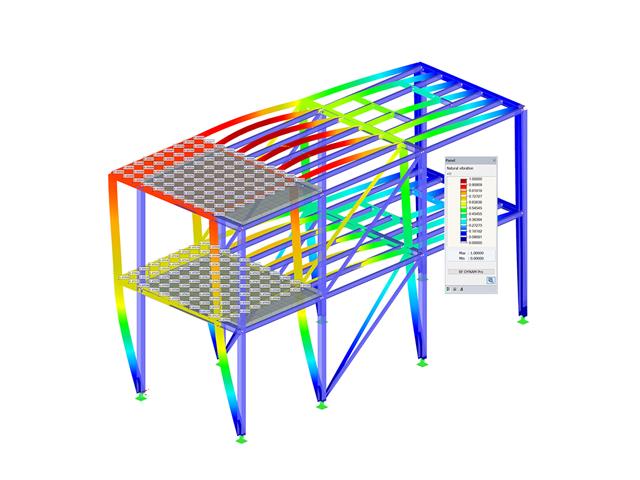
- Response spectra in accordance with different standards
- The following standards are implemented:
-
EN 1998-1:2010 + A1:2013 (European Union)
-
DIN 4149:1981-04 (Germany)
-
DIN 4149:2005-04 (Germany)
-
IBC 2000 (USA)
-
IBC 2009-ASCE/SEI 7-05 (USA)
-
IBC 2012/15 - ASCE/SEI 7-10 (USA)
-
IBC 2018 - ASCE/SEI 7-16 (USA)
-
ÖNORM B 4015:2007-02 (Austria)
-
NTC 2018 (Italy)
-
NCSE-02 (Spain)
-
SIA 261/1:2003 (Switzerland)
-
SIA 261/1:2014 (Switzerland)
-
SIA 261/1: 2020 (Switzerland)
-
O.G. 23089 + OG 23390 (Turkey)
-
SANS 10160-4 2010 (South Africa)
-
 SBC 301:2007 (Saudi Arabia)
 -
GB 50011 - 2001 (China)
-
GB 50011 - 2010 (China)
-
NBC 2015 (Canada)
-
 DTR BC 2-48 (Algeria)
 -
DTR RPA99 (Algeria)
-
CFE Sismo 08 (Mexico)
-
 CIRSOC 103 (Argentina)
 -
 NSR - 10 (Colombia)
 -
IS 1893:2002 (India)
-
AS1170.4 (Australia)
-
 NCh 433 1996 (Chile)
-
- The following National Annexes according to EN 1998‑1 are available:
-
DIN EN 1998-1/NA:2011-01 (Germany)
-
ÖNORM EN 1991-1-1:2011-09 (Austria)
-
NBN - ENV 1998-1-1: 2002 NAD-E/N/F (Belgium)
-
ČSN EN 1998-1/NA:2007 (Czech Republic)
-
NF EN 1998-1-1/NA:2014-09 (France)
-
UNI-EN 1991-1-1/NA:2007 (Italy)
-
NP EN 1998-1/NA:2009 (Portugal)
-
SR EN 1998-1/NA:2004 (Romania)
-
STN EN 1998-1/NA:2008 (Slovakia)
-
SIST EN 1998-1:2005/A101:2006 (Slovenia)
-
CYS EN 1998-1/NA:2004 (Cyprus)
-
NA to BS EN 1998-1:2004:2008 (United Kingdom)
- NS-EN 1998-1:2004 + A1:2013/NA:2014 (Norway)
-
- User-defined response spectra
- Direction-relative response spectrum approach
- Relevant mode shapes for the response spectrum can be selected manually or automatically (5% rule from EC 8 can be applied)
- Generated equivalent static loads are exported to load cases, separately for each modal contribution and separately for each direction
- Result combinations by modal superposition (SRSS and CQC rule) and direction superposition (SRSS or 100% / 30% rule)
- Signed results based on the dominant eigenmode can be displayed
.png?mw=640&hash=eaf8e422e9b3dcfb04a920c1d3bf09c1bef0d59a)
General
- Beam to Column joint category: connection possible on the column flange as well as on the column web
- Beam to Beam joint category: optional arrangement of ribs on the opposite side
- Bolt sizes from M12 to M36 with the strength grades 4.6, 5.6, 8.8, and 10.9
- Arbitrary bolt hole spacing and edge distances
- Notching of the beam is possible
- Connection with pure shear loading, pure normal force load (tension joint), or possible combination of normal and shear forces
- Checking compliance with the requirements for pinned joints
- Check of the minimum and maximum bolt hole spacing and edge distances
Web cleat connections
- One or two vertical and up to 10 horizontal bolt rows possible at each leg
- Wide range of equal and unequal angles
- Possible to modify angle orientation
- Designs:
- Shear, bearing resistance, and tension design of bolts
- Shear, bending, and tension design of angles considering deduction of bolt hole
- Shear and tension design of girder web considering deduction of bolt hole
- Tension transmission into the column with the T-stub model
- Notching at the critical section
Fin plate connection
- One or two vertical and up to 10 horizontal bolt rows are possible
- Flexible size of the fin plate
- Location of the fin plate can be modified
- Designs:
- Shear and bearing resistance design of bolts
- Shear, bending, and tension design of fin plates considering deduction of bolt hole
- Stability analysis of long, slender fin plates
- Shear and tension design of girder web considering deduction of bolt hole
- Weld as fillet weld
- Notching at the critical section
End plate connection
- Two or four vertical and up to 10 horizontal bolt rows
- Flexible size of the end plate
- Location of the fin plate can be modified
- Designs:
- Shear, bearing resistance, and tension design of bolts
- Shear and bending design of end plates considering deduction of bolt hole
- Shear and tension design of girder web
- Tension transmission into the column with the T-stub model
- Weld as fillet weld
- Notching at the critical section
End plate connection with cleat
- Fixation of the beam by end plate with two bolts
- Flexible size of cleat and end plate
- Designs:
- Load introduction into the beam according to EN 1993-1-5, Chapter 6
- Support of the stabilizing moment by the bolts and welds at the end plate
- Cleat
- Cleat welds as fillet welds
- Tension transmission into the column with the T-stub model

SHAPE-THIN determines the section properties and stresses of any open, closed, built-up, or non-connected cross-sections.
- Section Properties
- Cross-sectional area A
- Shear areas Ay, Az, Au, and Av
- Centroid position yS, zS
- moments of area 2 degrees Iy, Iz, Iyz, Iu, Iv, Ip, Ip,M
- Radii of gyration iy, iz, iyz, iu, iv, ip, ip,M
- Inclination of principal axes α
- Cross-section weight G
- Cross-section perimeter U
- torsional constants of area degrees IT, IT,St.Venant, IT,Bredt, IT,s
- Location of the shear center yM, zM
- Warping constants Iω,S, Iω,M or Iω,D for lateral restraint
- Max/min section moduli Sy, Sz, Su, Sv, Sω,M with locations
- Section ranges ru, rv, rM,u, rM,v
- Reduction factor λM
- Plastic Cross-Section Properties
- Axial force Npl,d
- Shear forces Vpl,y,d, Vpl,z,d, Vpl,u,d, Vpl,v,d
- Bending moments Mpl,y,d, Mpl,z,d, Mpl,u,d, Mpl,v,d
- Section moduli Zy, Zz, Zu, Zv
- Shear areas Apl,y, Apl,z, Apl,u, Apl,v
- Position of area bisecting axes fu, fv,
- Display of the inertia ellipse
- First moments of area Qu, Qv, Qy, Qz with location of maxima and specification of shear flow
- Warping coordinates ωM
- moments of area (warping areas) Sω,M
- Cell areas Am of closed cross-sections
- Normal stresses σx due to axial force, bending moments, and warping bimoment
- Shear stresses τ from shear forces as well as primary and secondary torsional moments
- Equivalent stresses σv with customizable factor for shear stresses
- Stress ratios, related to limit stresses
- Stresses for element edges or center lines
- Weld stresses in fillet welds
- Section properties of non-connected cross-sections (cores of high-rise buildings, composite sections)
- Shear wall shear forces due to bending and torsion
- Plastic capacity design with determination of the enlargement factor αpl
- Check of the c/t-ratios following the design methods el-el, el-pl or pl-pl according to DIN 18800